: Single phase AC Motor speed controller :~
Abstract: - here is a very simple example of AC motor speed control given by changing firing angle of TRIAC with the help of micro controller 89C2051. Varying speed of AC motor by means of changing firing angle of any thyristor is very widely used method. One very nice example is fan regulator in which a fan motor is 1 AC motor used and its speed is varied using DIAC-TRIAC method. Here instead of using DIAC and other components for firing TRIAC here I am using micro controller 89C51 for this purpose.
A zero crossing detector circuit is used here to interrupt 89C2051 after every 10 ms. After getting an interrupt 89C51 will fire TRIAC after some delay from 1 to 9 ms. This will cut the current supplied to motor and so the speed of motor will reduce. Thus by varying the delay after which the TRIAC is triggered one can change the speed of motor.
___________________________________________________
Main circuit is a combination of two sub circuits.
- Zero crossing detector circuit
- Firing angle control circuit
Zero crossing detector circuit: -

Connections: - as shown in above figure transformer T1 step downs 230 VAC in to 9 VAC and this is given to bridge rectifier D1. This rectified output is directly fed to base of Q1 through resistors R1 & R2. Same rectified output is filtered through C1 and given to voltage regulator IC 7805. Output of 7805 is regulated 5 VDC that is given as biasing voltage for both transistors Q1 & Q2 (same regulated 5 V supply is given to main control section also). Both transistors are connected in switch configuration. The final output ‘C’ is given to main control section.
Firing angle control circuit: -

Connections: - as shown in above figure micro controller 89C2051 along with opto coupler MCT2E (for triggering TRIAC) and common cathode type bar graph display (for indicating angle) are used for changing firing angle of TRIAC. Signal 'C' from zero crossing detector circuit is directly given to pin no. 6 that is external interrupt 0 (P3.2) pin. All port P1 pins are connected with anodes of bar graph display and common cathode of bar graph is grounded. One led LED1 is connected with P3.0 as shown. Pin P3.1 is connected with input of opto-coupler MCT2E. Output of MCT2E is connected with gate of TRIAC. TRIAC is connected in loop with AC motor and 230 VAC supply as shown. RC snubber circuit is connected is connected in parallel with TRIAC. Three push buttons S1 - S3 are connected with P3.4, P3.5 & P3.7 respectively through diodes. Pin P3.3 (external interrupt 1) is connected with all three push buttons through diodes D1, D2 & D4 as shown. A 12 MHz crystal along with 2 33pf capacitor is connected with crystal input pins. Capacitor C1 with push buttons RST forms power on reset circuit.
Operation: - to understand operation let us take a help of waveforms.

- As shown in figure the first wave form is full rectified wave that is fed to the base of Q1. Whenever this voltage falls below 0.7 V Q1 is switched off. So its output goes high.
- This will produce one very short positive pulse at ‘B’ as shown in figure as second waveform
- As this positive pulses are fed to Q2 which is again connected in switch configuration, it will produce one negative pulse at ‘C’ of same width of positive pulse. This is shown as third waveform
- Now as this negative pulse output is given to interrupt pin of micro controller. It will generate interrupt every time.
- After getting an interrupt micro controller will generate a positive pulse on P3.1 after some delay. This will turn off internal LED and due to that a positive pulse is produced at output. This is used to trigger (fire) TRIAC
- Depending upon the time delay in between interrupt and pulse on P3.1, the TRIAC is fired earlier or later.
- As shown In figure I have given wave forms for two different cases one for 4 ms delay and second for 8 ms delay
- In the first case for 4 ms delay the output positive cycle of AC wave is 60% of input so only 60% current is delivered to load (the dotted line shows part of wave form that has been cut)
- For second case 8 ms delay output cycle is 20% of input cycle so only 20% current is supplied to load
This change in delay is done through push buttons given. So let us see the functions of push button
| Switch | Functions |
| S1 | to switch on / off TRIAC |
| S2 | to increase delay by 1 ms |
| S3 | to decrease delay by 1 ms |
Led LED1 is used to indicate the TRIAC is on. Variation in angle is displayed on bar graph display. If angle is more, less current supplied to motor and motor speed is reduced less bars appears on display. If angle is decreased, current supplied will be more, speed of motor is increased and more bar appears on display.
The diodes D2 – D7 are connected in such a manner that whenever any of three push buttons, is pressed it will generate external interrupt 1.
When S1 is pressed first time it will enable external interrupt 0. So after every 10 ms external interrupt 0 is generated and that will start the entire operation. Pressing S1 again will disable external interrupt 0. Now no more interrupt is generated and complete operation is shut off.
On pressing S2 will increase delay by 1 ms (firing angle by 18o deg). So firing of TRIAC is delayed by 1 ms and amount of current supplied to load is decreased by 10%. Maximum delay is 9 ms (max angle is 162o deg). Bar is increased by 1 step.
In same manner when S3 is pressed delay is decreased by 1ms (firing angle by 18o deg) and load current increases by 10%. Minimum delay is 0 means full positive cycle is applied. Bar is decreased by 1 step.
The bar graph displays the variation in phase angle. More bars means angle is big and motor speed is low and vice versa.
Software logic: -
The complete operation is based on the software embedded in micro controller 89C2051. The software is written in C language. Different functions are used for different operations like ext1, ext0, delay and keydly etc. Here is the code with necessary comments which it self explains all above functions.
~: AC Motor control program in C :~
#include<reg51.h>
#include <string.h>
sbit led1 = P3^0;
sbit s1 = P3^4;
sbit s2 = P3^5;
sbit s3 = P3^7;
unsigned int d1=0;
unsigned int d2=0;
unsigned int c=0;
bdata unsigned char byte;
sbit b0 = byte^0;
void dely(void);
void incangle(void);
void decangle(void);
void delay(int d);
void keydly(void) //key debounce delay
{
unsigned int x,y;
for(x=0;x<100;x++)
for(y=0;y<1000;y++);
}
void decangle() //decrease delay by 1ms
{
EX1=0; //first disable all interrupts
if(d1>0)
{
d1--; // decrease delay
shiftdown();
P1=byte;
}
EX1=1; // enable interrupts before leaving
}
void incangle() // increase delay by 1 ms
{
EX1=0; // all other things remains same as above
if(d1<9)
{
d1++;
shiftup()
P1=byte;
}
EX1=1;
}
void delay(int d) // generates delay from 1 to 9 ms
{
int k;
TL0 = 0x17; // load timer 0 with 64535 = FC17h
TH0 = 0xFC; // so it will overflow after 1000 counts
TR0 = 1; // start timer
for(k=0;k<d;k++) // count overflows of timer 0 till
{ // desire delay is required
while(TF0==0);
TF0 = 0;
TL0 = 0x17;
TH0 = 0xFC;
}
TR0 = 0;
}
void int0(void) interrupt 2 // external interrupt 1 subroutine
{
keydly(); // after key debounce delay
if(s1==0) // for first key
{
c++; // increase counter
if((c%2)==1) // check even or odd
{
EX0 = 1; // enable external interrupt 1 if odd
}
else
{
EX0 = 0; // disable external interrupt 1
}
}
else if(s2==0) // for second key
{
incangle(); // increase phase angle
}
else if(s3==0) // for third key
{
decangle(); // decrease phase angle
}
}
void int1(void) interrupt 0 // external interrupt 1 subroutine
{
int t;
led1=0; // led1 is on
delay(d1); // after desired delay
pulse=1; // send pulse on p2.0
for(t=0;t<200;t++);
pulse=0;
led1 = 1; // led1 off
}
void main()
{
TMOD = 0x01; // initialize timer0 as 16 bit timer
P1=0x00; // P1 as output ports
P3=0xFF; // P3 as input port
IE=0x84; // enable external interrupt 1
while(1); // continuous loop
}
Reference -multyremotes
-------------------------------------------------------------------------------------------------------------------------------------------------------------------------------------------------------------------------------------------------------------------------------------------------------------------------------------------------------------------------------------------------------------------------------------------------------------------------------------------------------------------------------------------------------------------------------------------------------------------------------------------------------------------------------
controlling of stepper motor without programming.
In this circuit the 74HC74 directly drives the stepper motor for low power applications. The two flip-flops are alternately clocked to give the desired "follow-the-leader" pulse train. The 16.8 volt motor (1.8 degree step size) described above draws only 20 mA in this circuit and a tiny 15 degree step size, 12 volt motor only draws 30 mA. The unused inverters are wired to form a slow pulse generator which may be used to randomly change the direction of rotation. Actually, the change of direction will often synchronize with the spin oscillator giving a back-and-forth action unless the oscillator frequency is just right. This change of direction will add interest to moving displays.
The circuit generates four control signals and adding circuitry for high power operation is fairly easy. If a center-tapped motor is used then the following connection will work:
You will need one of these circuits for each motor winding. If the motor doesn't have a center-tap then try the circuit below. The values are only representative and may vary depending upon the motor and transistor gain. No provisions are shown to protect against inductive kickback but small motors don't seem to generate much. However, some care may be required if larger motors and higher currents are used. Consider adding diodes from each motor winding to Vcc (the cathode goes to Vcc). Also, the 2N440Xs are only good for a few hundred milliamps so choose heftier transistors and use lower value resistors if higher motor currents are expected.
The flip-flop shown is an HC device and its power supply should be limited to 5 or 6 volts but the flip-flop could be a 4000 series device if driver transistors are added. The 4000 series devices cannot supply much current but they will run on +15 volts. Increase the resistors to 10k and use darlington transistors (or mosfets such as the VN10KM) in place of the NPNs shown.
----------------------------------------------------------------------------------------------------------------------------------------------------------------------------------------------------------------------------------------------------------------------
How to Build a PC Controlled RC Car
August 2004
Introduction
The Mini RC Car Project has been one of my favorites to do. If you haven't checked that project out, please read through that one before starting on your own. I've gotten a few e-mails requesting a guide and since the software is done, all that is required is to construct the hardware. This is the second time I've done this project, using totally two completely different cars. The remote PCBs (electronics) were almost identical in both, so I'm assuming most all mini rc remotes are very similar, so this guide should be able to apply to all makes and models.
Tools and Materials Required
| - Mini RC Car & Remote - (5) Wires 1-2ft long (or 1 cat5 network cable) - Misc. small wires - Drill - Wire Stripper (or knife) - Screwdriver(s) -Scissors or Wire Cutters -Small piece of plastic or plexi-glass - *Some basic soldering skills | - Soldering Iron - Solder - (4) 2N3904 NPN Transistors - (1) Small solder board - Male Parallel Port Connector - Digitial Multimeter if Avaliable Total Cost: (not including tools) Approx - $20.00 cdn |
 (Most of the tools required, all laid out) |  (Retract-a-bit Mini Screw Driver. Very Useful) |
 Transistors and Solder Board |  Male Parallel Port Connector |
 Drill |
Step One: Open Remote and Expose PCB
With the antena unscrewed, remove the 3 screws from the back of the remote. You will need a fairly small screwdriver.
 1 - Screw Hole Locations |  2 - Buttons and Screw |  3 - Attached still |
 4 - The PCB is free |
The following corresponds to the pictures above:
1 - Screw Hole Locations
Remove the screws and the remote face should come off easily.
2- Take note of the button locations and remove the bottom right screw holding the PCB in place.
3- The PCB is still attached. Snip the wires close to the circuit board, but leave enough of the wire to identify the colour, for when re-attaching later.
4- The PCB should now be free, making it easier to work on.
Step Two: Drilling the Remote Case
 | In order to get a cable that goes from the back of the remote's PCB to the computer, we need to make a hole in the remote's plastic case for the wires to go through. Any size hole will do, as long as it's big enough for your wires to fit through. Drill the hole closer to the back of the remote, if possible. That just makes it so the cable won't have to bend as much. |
Step Three: Soldering to the Board
| Strip the ends of the wires. Five wires, about 1-2 ft in length are needed. I used a Cat-5 network cable that has 8 wires in it, but only 5 are required. | 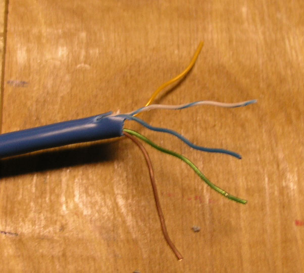 |
| Turn over the PCB (printed circuit board). Under each button there are four solder joints. These are actually (2) sets of (2) joints. These are highlighted in the picture on the right. Identify the wire that the negative side of the battery was connected to (see wire indicated in the picture). This will connect to one of the large green areas on the board. For each switch, two of the solder joints will be located in this green region. Leave those joints alone. |  (Click for a Larger Image) |
 (Click for a Larger Image) | What we are concerned with, is the positive "side" of the switch. For each switch, you need to identify which side is negative and which is positive. Solder a wire onto each positive side and one wire to a negative terminal (there are many negative terminals on the PCB, it doesn't matter which you choose). You should have 1 wire per switch soldered, and one wire to the negative terminal. My board, with the wires soldered can be seen to the left. Boxes are drawn in to show the same groups of four shown above. |
Step Four: Build the PC Interface
This is the most callenging part of the project.
Before you start building the cable, feed the wires you soldered, through the hole you drilled earlier. This will allow you to put it all back together again at the end.
Before you start building the cable, feed the wires you soldered, through the hole you drilled earlier. This will allow you to put it all back together again at the end.
 | Take the male parallel port connector and solder short wires to pins 2,3,4,5,23. Pins 2-4 will carry the data (forward, reverse, left, right) and pin 23 is ground. Side note: when doing any pc-parallel port interfacing, pins 2-9 are easily controlled data pins and pins 18-25 are all ground. Other pins have specialty functions and can be used in interesting ways. When completed, it should look similar to the picture on the left. | |
 | Parallel Port Pinout (Click for Larger Image) | |
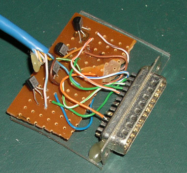
The rest consists on building a circuit, using the schematic (diagram) I have made up. For this you need, a bunch of small wires, solder board, (4) 2N3904 NPN Transistors. Print out the schematic below and build the circuit. (Note: the ground is the Parallel Port Pin 23 and Remote Negative Terminal connected together, there is no 'third' ground.)
 (Click for a Larger Image) |
Pictures of Circuit Construction:
Follow the schematic, but these may help you out. These pics do not show full construction.
Follow the schematic, but these may help you out. These pics do not show full construction.
|  |
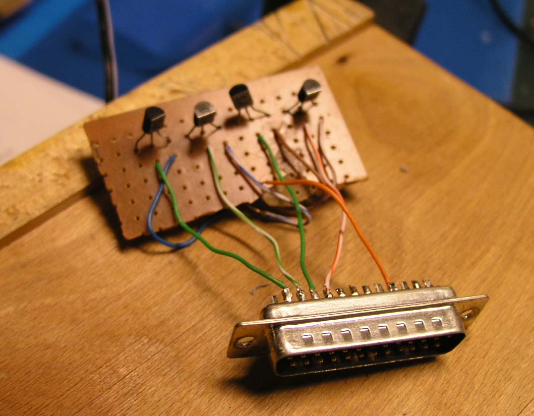 |  |
If you've followed the schematic and completed the following steps properly, all we have left to do is re-attach the wires cut at the beginning and put everything back together.
Step Five: Reattaching the Wires
In the first step, you cut some wires. Those will now need to be re-attached. I would suggest replacing them with your own wires and use longer ones. The factory wires are very cheap and it's a lot easier just to use wires double as long, so you have enough room to solder them to where the old wires use to be. You can always just strip the old wires are re-attach using electrical tape, but I think my way is easier. The choice is up to you.
Step Six: Reassembly
 | The remote needs to be re-assemled. Squish down all the wires down on the back of the PCB and put the screw back in. It might take several tries to get it flat enough, because there's a lot more wires back there than there use to be. Put back on the plastic remote face and replace the screws in the back of the remote. The remote should look very much like how it started, but with a large bunch of wires sticking out the side. |
 | After the remote is put back together, the hardware aspect of the project is complete! |
Making it Look Nice
 | To make it easier to plug in, it's best to have a solid unit to plug into the back of the computer. I took a small piece of plexi-glass and glued all the components to it to make it sturdier, easier to handle and it makes it look a whole lot better. |
 |
Software
The remote will still function normally if you use it just by pressing the buttons, but to control it with the computer, software is needed. For my grade 11 final computer science project, I built this hardware and wrote the software to control it. To control what you've just constructed, you will need the software as well. It is avaliable in the downloads section. To make the software work, you need to know the port address of your parallel port. In the documention included (documention.doc, in the zip file), there are clear instructions how to find this address. The most common address (888) is the default. The software was written in Visual Basic 6, and was recently updated to run on all windows operating systems.
Quick Lesson: How it Works
With the software, the computer sends a signal from the parallel port to the transistor. The transistor closes the circuit between the ground and the positive side of the button switch. This is the exact same thing that happens when you press the button manually. So essentially, the computer is pressing the buttons for you. Because we can control the computer, it means we can make the car programmable and other neat stuff like that.
Conclusion
I hope you've enjoyed this guide and learned something along the way. If you do construct your own Computer Controlled RC Car, and send me a pic I will post in on the site. If you have any feedback or questions let me know and I'll be glad to help. If you have any difficulties along the way, let me know and I'll try to help you out. Controlling the parallel port is quite easy and it opens to door to a whole lot of PC-Hardware interfacing. With transistors, you can control motors or other electronics. My latest pc interfacing project was my grade 12 computer science project, which was to control an LED matrix of 140 LEDs, with just the handful out outputs of the parallel port (some additional electronics were required). That project will soon be posted in the projects section.