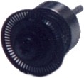
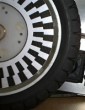
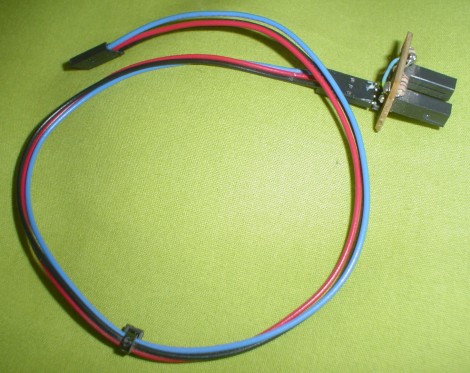
 The Robot Encoder - What is it? The encoder is a sensor attached to a rotating object (such as a wheel or motor) to measure rotation. By measuring rotation your robot can do things such as determine displacement, velocity, acceleration, or the angle of a rotating sensor. A typical encoder uses optical sensor(s), a moving mechanical component, and a special reflector to provide a series of electrical pulses to your microcontroller. These pulses can be used as part of a PID feedback control system to determine translation distance, rotational velocity, and/or angle of a moving robot or robot part. For instance, if you have a wheel rotating, and you want to measure the time it takes to rotate exactly 40 degrees, or know when you have traveled X distance, you would use an encoder. The sensor would be fixed on your robot, and the mechanical part (the encoder wheel) would rotate with the wheel. The output of an encoder would be a square wave, so if you hook up this signal to a digital counter or microcontroller you can then count the pulses. Knowing the distance/angle between each pulse, and the time from start to finish, you can easily determine position or angle or velocity or whatever. Encoders are necessary for making robot arms, and very useful for acceleration control of heavier robots. They are also commonly used for maze navigation. Calculating Robot Motion with an Encoder For every pulse sent out by the encoder, your rotating wheel has traveled a certain angle. So how do you calculate the distance a robot traveled for each click the encoder recieved? If the encoder gives 5 clicks in one second, how fast is your robot going? To do this calculation you need more information, such as wheel diameter andencoder resolution (number of clicks per 360 degrees, or counts per revolution). I highly recommend reading the first half of my Robot Dynamics tutorial before continuing on to understand how wheel diameter relates to robot speed. Starting off, you should know two things - wheel circumference and counts per revolution. Dividing the two, you can easily figure out the distance your robot travels between each encoder click: wheel circumference / counts per revolution = distance traveled per encoder count Now velocity is just distance divided by time . . . So using the answer in the above equation, divide that by the time passed determined from your microcontroller timer: distance traveled per encoder count / time = velocity After you know distance and velocity, you must then run a PID feedback control algorithm so that your robot can match a desired (pre-determined) distance and velocity.
  | To better help you, check out theencoder calculator to aid you with your robot specs. |
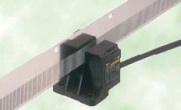
 And a closeup of the connection:
 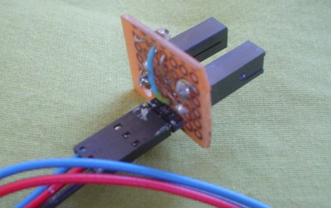 Encoders With a Microcontroller It is highly recommended to read the tutorial on programming timers and PID control. How to Make an Encoder Wheel
 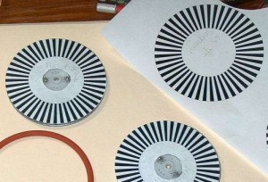 1) Download the basic excel pie chart encoder or make your own. 2) Modify it to get the desired resolution (add more 1's and 0's). 3) Move the pie chart as an image to paint, and color each as black and white. 4) Print it out on transparencies, and cut it out. 5) Make sure you cut the hole in the center perfectly or you will have problems later of wobbling. 6) Trace over the black with several layers of infrared absorbing ink, akapermanent marker. 7) Place the encoder wheel on your rotating shaft, and use a slot IR sensor to count wheel rotation. 8) Make sure the resistor value on your IR sensor circuit is chosen right to work with the permanent marker ink. These are a few encoder wheel designs I printed out to try:
 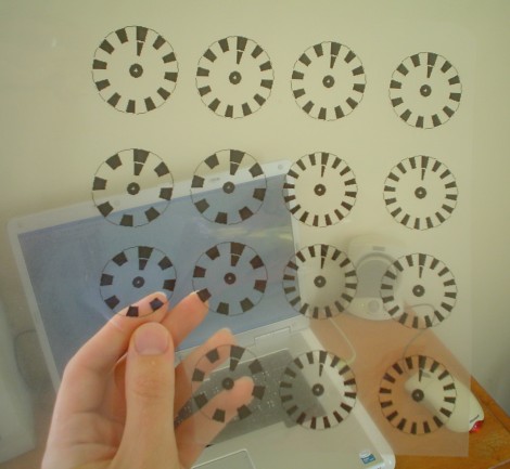 I have also found a really neat encoder design program written by this guy namedScott Boskovich. It is way better than the excel method. Give it a try!
 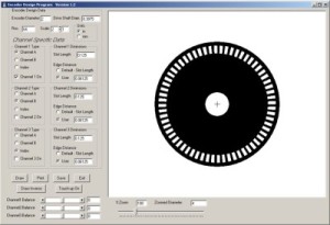 If you expect a motor rotation to often go to a certain angle, you can also put interesting patterns on your encoder wheel to make processing simpler. You can use an IR LED array IC to read all the patterns simultaneously.
Reference - society of robot.